Actions, 3D Icons, and Shelves
Most of the interaction in EasyMaker3D is initiated by clicking on one of the 3D icons on the various shelves in the work area. (See that section in the Overview for the shelf names and locations.)
Each of the 3D icons represents an action that makes some sort of change to the scene or program state. These actions can be divided into these general types:
A toggle action changes some program state that is either on or off. For example, the Show Edges toggle action turns the visibility of polygonal edges on models on or off.
A tool action selects a tool to attach to the currently-selected model(s).
A panel action brings up a 2D panel that provides some special interface.
All other actions produce some sort of immediate change to models, the selection state, or the session state.
All actions can be applied from a radial menu, and many have corresponding keyboard shortcuts. The Cheat Sheet lists all supported actions along with their names, radial menu icons, and keyboard/controller shortcuts. The actions are divided into categories, some of which correspond to shelves in the work area. Note that some actions do not have corresponding 3D icons; they can be performed only from a radial menu or shortcut.
Certain actions may not be enabled due to the current application state. A 3D icon for an enabled action will appear with the regular light woodgrain texture. An icon for a disabled action will be dark instead. 3D icons that represent enabled toggle actions will be colored green when the toggle is in the “on” state and regular woodgrain when in the “off” state.
The following sections detail what each action does in the application, divided by category.
Basic Actions
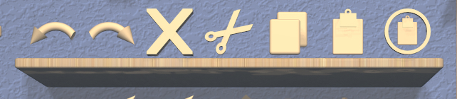
EasyMaker3D provides most of the basic operations you would expect in an interactive application. Each of these is available by clicking on a 3D icon on the Basic Operations shelf on the top of the back wall in the work area. From left to right, these are:
The Undo action undoes the last operation performed that modified the scene in some way.
The Redo action redoes the last undone action.
The Delete action deletes all selected models from the scene. They are gone forever, unless you undo.
The Cut action copies all selected models from the scene to the clipboard and removes them from the scene.
The Copy action copies all selected models from the scene into the clipboard.
The Paste action pastes all models from the clipboard into the scene as top-level models at their previous 3D locations.
The Paste Into action can be used to paste models from the clipboard as children of the primary selection model, as long as that model is one that can have children. For example, if you have a CSG union model and you want to add a Box model to it, you can cut or copy the box in its correct position, select the CSG model, and click the Paste Into icon. The box will be added as a child of the union and therefore become part of the CSG operation.
In addition, the Quit action (avalable via shortcut or radial menu) exits the program after checking for unsaved changes. This is equivalent to clicking on the exit sign in the work area.
Note that Undo and Redo actions apply to these operations:
Any change to a model or models.
Changing the position or any other aspect of either of the targets.
Actions that are not considered changes and are therefore not undoable include:
Changing the view.
Changing the orientation or size of the stage.
Selecting or deselecting models. (However, undoing or redoing other actions may affect the current selection.)
Toggling any program state, such as target or edge visibility.
Applying the Copy action, since it has no visible effect except to update the clipboard. Note that you may be able to use this to your advantage.
Hovering over the Undo or Redo icon (when enabled) shows a tooltip describing what operation will be undone or redone.
Combination Actions
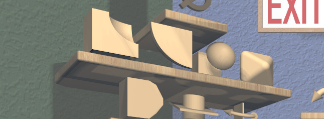
Actions to create a combined model from the selected models are available as 3D icons on the second shelf from the top on the left wall in the work area. From left to right, they are:
The Combine CSG Difference action applies the CSG difference operation to all selected models and attaches the CSG Tool to the resulting CSG model. Note that this operation is not symmetric, so it depends on the selection order.
The Combine CSG Intersection action applies the CSG intersection operation to all selected models and attaches the CSG Tool to the resulting CSG model.
The Combine CSG Union action applies the CSG union operation to all selected models and attaches the CSG Tool to the resulting CSG model.
The Combine Hull action applies the convex hull operation to all selected models. There is no specialized tool for a hull model, so the current general tool is attached to the resulting model.
The CSG actions require at least two models to be selected, but the convex hull action can be applied to a single model.
Conversion Actions
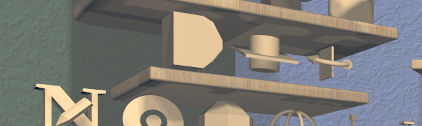
The center shelf on the left wall of the work area has 3D icons that apply actions to create converted models from the selected models. Applying any of these actions converts all selected models to a specific type and then attaches the corresponding specialized tool to the primary selection. From left to right, they are:
The Convert Bevel action converts all selected models to Beveled models and attaches the Bevel Tool to the primary selection.
The Convert Clip action converts all selected models to Clipped models and attaches the Clip Tool to the primary selection.
The Convert Mirror action converts all selected models to Mirrored models and attaches the Mirror Tool to the primary selection.
Creation Actions
Model Creation actions are all available as 3D icons on the two shelves on the bottom of the left wall of the work area. Each creates a model of a specific type
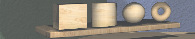
From left to right on the bottom shelf, the icons/actions are:
Box model (Create Box)
Cylinder model (Create Cylinder)
Sphere model (Create Sphere)
Torus model (Create Torus)
From left to right on the next shelf up, the icons/actions are:
Surface of revolution model (Create Rev Surf)
Extruded model (Create Extruded)
Text model (Create Text)
Imported model (Create Imported Model)
Clicking on any of these icons creates a new instance of the corresponding type of model, which drops in from above. If the Point Target is visible, the new model will end with its bottom center point at the targets’s position and with the model’s +Z (“up”) direction aligned with the Point Target’s direction.
The new model automatically becomes the primary selection. If the model type has a specialized tool associated with it, that tool will automatically be attached to it. Otherwise, the current general tool will be attached.
Layout Actions
The following actions are available as 3D icons on the Layout shelf, which is the middle shelf on the back wall. From left to right:
The Toggle Point Target action changes the visibility of the Point Target.
The Toggle Edge Target action changes the visibility of the Edge Target.
The Linear Layout action uses the Edge Target to lay out selected models along a line. See the section on linear layout for details.
The Radial Layout action uses the Point Target to lay out multiple selected models along a circular arc or to move a single model to the target. See the section on radial layout for details.
The Toggle Axis Aligned action changes whether certain tools operate in the selected model’s local coordinates or in stage coordinates. For example, if a model has been rotated to an arbitrary orientation and you want to move it 5 units to the right in the scene, you can turn this toggle on and the Translation Tool will then align its geometry and motion with the stage axes, not the model’s local axes. This toggle affects the Clip Tool, Mirror Tool, Rotation Tool, and Translation Tool.
One other layout-related action is available only via a keyboard shortcut or radial menu:
The Move To Origin action translates the primary selection so that the center of its bounds is centered over the origin (center of the stage) without rotating and the lowest point of its bounds is resting on the stage. Any secondary selections are moved by the same amount.
Modification Actions
Certain actions that immediately modify the currently selected models are available only via keyboard shortcuts or radial menus:
The Increase Complexity and Decrease Complexity actions increase or decrease the complexity of all selected models by .05 (within the 0-1 range). This can be a quicker way to modify complexity than by using the Complexity Tool.
The Move Next and Move Previous actions can be used to change the order of top-level models or child models within the same parent model. These actions are also available with buttons in the Tree Panel.
Precision Actions
The current precision level can be changed with the Increase Precision and Decrease Precision actions. These are available via keyboard shortcuts, radial menus, or by using the Precision Control on the back wall of the work area.
Selection Actions
The following actions that modify the current selection are available only via keyboard shortcuts or radial menus.
The Select All action selects all top-level models (in order). If any models are already selected, they remain selected and all unselected top-level models are added as additional secondary selections.
The Select None action deselects all selected models.
The Select First Child, Select Next Sibling, Select Previous Sibling, and Select Parent, actions can be used to change selections through model hierarchies.
Note that the Tree Panel can be used to view and change the current selection, especially in a model hierarchy.
Session Actions
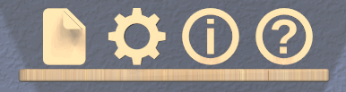
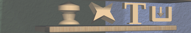
The following four actions are available as 3D icons on the Session shelf, which is the bottom shelf on the back wall. From left to right:
The Open Session Panel action displays the Session Panel, which allows you to save your session, load a new session, and so on.
The Open Settings Panel action displays the Settings Panel, which allows you to edit application settings.
The Open Info Panel action displays the Info Panel, which shows information about currently selected models and the targets.
The Open Help Panel action displays the Help Panel, which displays the application version and has buttons to open this guide or the Cheat Sheet in your default browser.
Specialized Action
Each specialized tool can be attached only to a specific type of model. When a model of that type is created, the corresponding specialized tool is attached to it automatically.
The Toggle Specialized Tool action switches between the specialized tool for the current selection and the current general tool. This action is disabled if any selected model has no specialized tool or if multiple models are selected and they are not all of the same type.
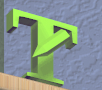
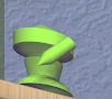
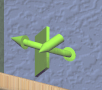
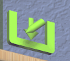
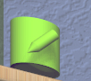
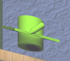
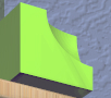
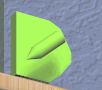
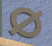
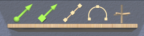
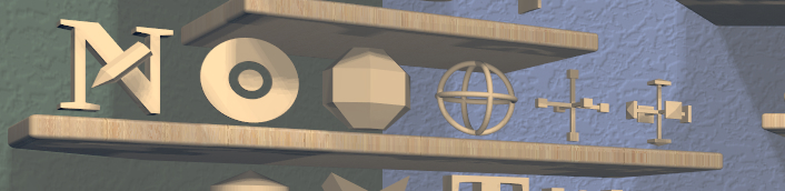
Clicking on the 3D icon on the top shelf on the left wall applies the toggle action if available. This icon changes shape to reflect what the toggle will do. It will be one of the icons shown here, from left to right:
The null icon is shown when no model is selected or no specialized tool that can be applied to the current selection. It is always disabled.
The Bevel Tool icon is shown when the current selection consists of only Beveled models.
The CSG Tool icon is shown when the current selection consists of only CSG models.
The Clip Tool icon is shown when the current selection consists of only Clipped models.
The Cylinder Tool icon is shown when the current selection consists of only Cylinder models.
The Import Tool icon is shown when the current selection consists of a single Imported model.
The Mirror Tool icon is shown when the current selection consists of only Mirrored models.
The Rev Surf Tool icon is shown when the current selection consists of only RevSurf models.
The Text Tool icon is shown when the current selection consists of only Text models.
The Torus Tool icon is shown when the current selection consists of only Torus models.
All but the null icon will be shown with the active icon color when the corresponding specialized tool is attached and the regular woodgrain icon color when toggled back to a general tool.
Note that the Space shortcut is an easy way to toggle between general and specialized tools when enabled.
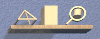
Tool Actions
Actions to choose the current general tool are available as 3D icons on the second shelf from the bottom on the left wall of the work area. Clicking on any of these icons attaches the corresponding general tool to the primary selection. Note that most of these tools affect all secondary selections in addition to the primary model.
From left to right the tool icons are:
The Name Tool action attaches the Name Tool <ug-name-tool> to edit the name of the primary selection.
The Color Tool action attaches the Color Tool to change the color of all selected models.
The Complexity Tool action attaches the Complexity Tool to change the tessellation of all selected model(s). (Note that only Cylinder, Sphere, Torus, RevSurf, and text models respond to complexity changes; the action is disabled if only other types of models are selected.)
The Rotation Tool action attaches the Rotation Tool to rotate all selected models.
The Scale Tool action attaches the Scale Tool to change the size of all selected models.
The Translation Tool action attaches the Translation Tool to change the position of all selected models.
In addition, the Switch To Next Tool and Switch To Previous Tool actions are available via keyboard and controller shortcuts to quickly cycle through the available general tools for the current selection.
Viewing Actions
The 3D icons on the Viewing shelf (above the Tree Panel on the back wall) apply actions that deal with viewing models. From left to right:
The Toggle Show Edges action lets you show or hide model edges as visible lines.
The Toggle Build Volume action lets you show or hide the translucent representation of your 3D printer’s build volume.
The Toggle Inspector action lets you turn on inspector mode for the current primary selection.
Other viewing actions are available only via keyboard shortcuts or radial menus:
The Hide Selected action makes all currently selected top-level models temporarily invisible.
The Show All action makes all top-level models visible again.
Note that the Tree Panel can also be used to hide or show models.