EasyMaker3D Quickstart
Installing and Running EasyMaker3D
Open the the download site (on Google Drive) in a browser and download the Zip file for your operating system. Extract all files wherever you like; this will create a EasyMaker3D folder. In this folder there is a EasyMaker3D executable that you can click on to run the application.
A Simple Doorstop Example (Non-VR)

This example will use EasyMaker3D in non-VR mode to create a simple doorstop model and output it as an STL file.
Clicking on any of these images will show an enlarged version.
Start the Application
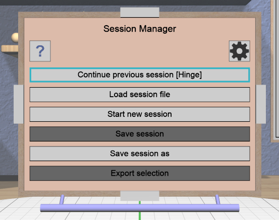
Starting the application should open a maximized window that you can interact with using the keyboard and mouse. The first thing you should see is this panel that lets you interact with sessions. Click on the Start new session button to start a new session (or just hit the Escape key).
Create and Position a Torus
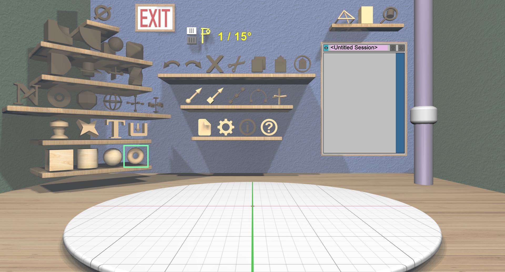
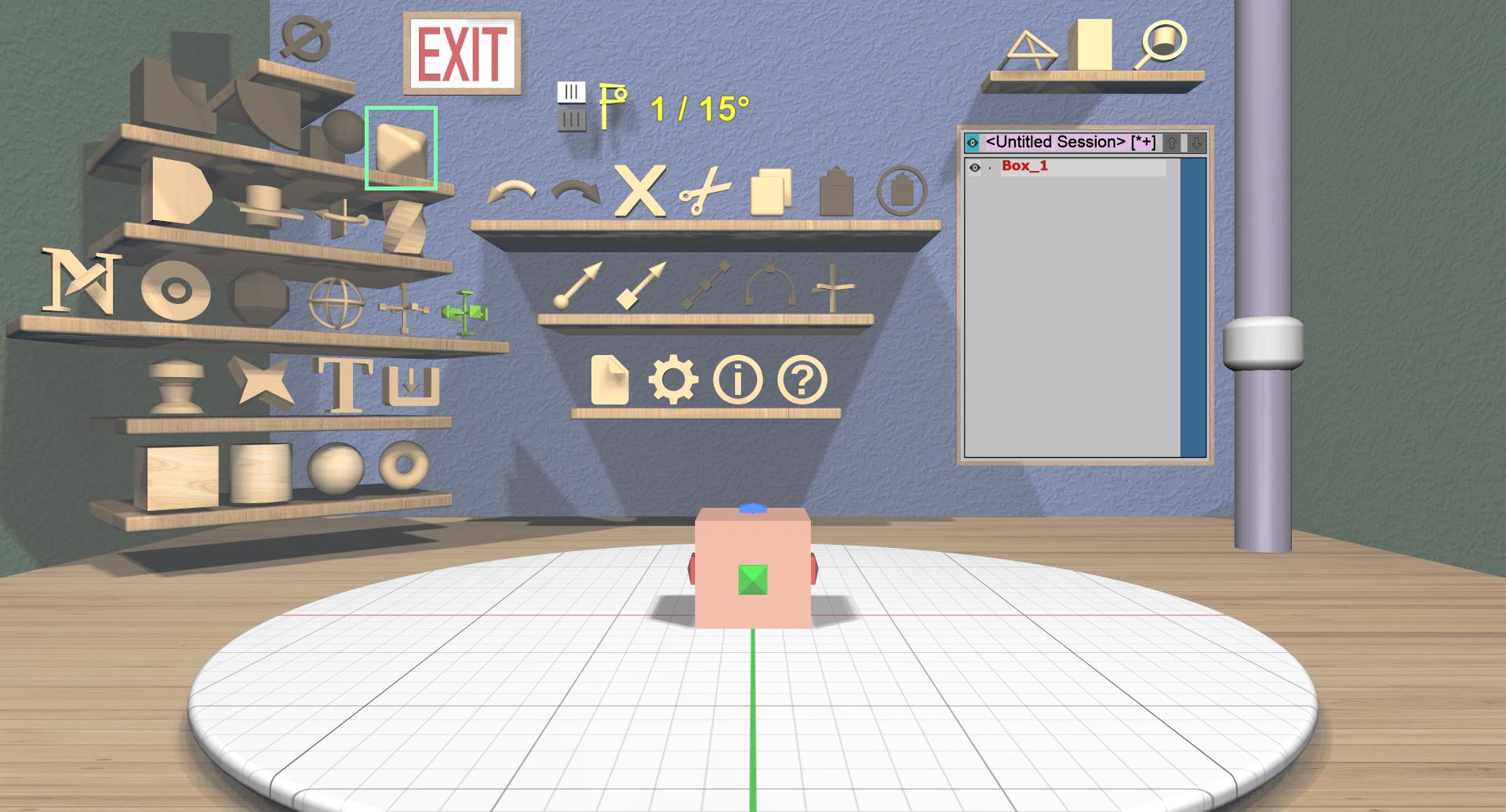
Click on the 3D torus icon on the bottom-left shelf to drop a new torus model into the scene. The torus will have some interactive handles attached to it that you can use to change the sizes of the outer and inner diameters. You can leave them at their default sizes for this example. If you change them and want to undo your changes, you can click on the 3D undo icon on the top shelf on the back wall or use Ctrl-Z.
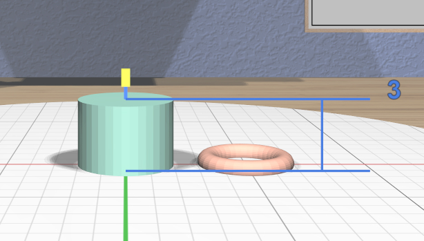
Next you will move the torus a little to the right. Hit Space to switch from the specialized torus tool to the general translation tool.
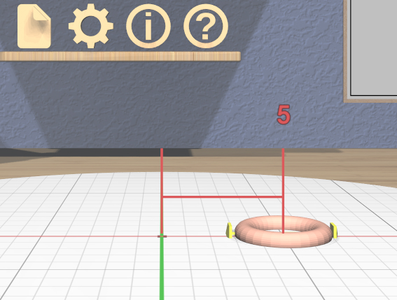
Drag the handle on the right side of the torus to the right until it has moved 5 units. You will notice that as you drag the torus, feedback appears to show you the direction and distance you have moved, as shown here.
Create a Cylinder and Change Its Size

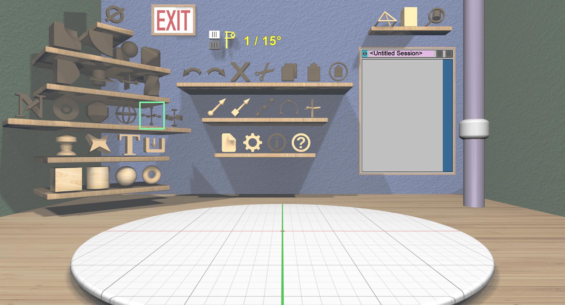
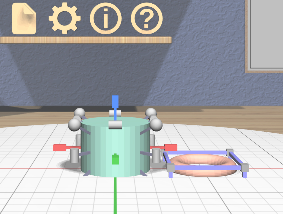
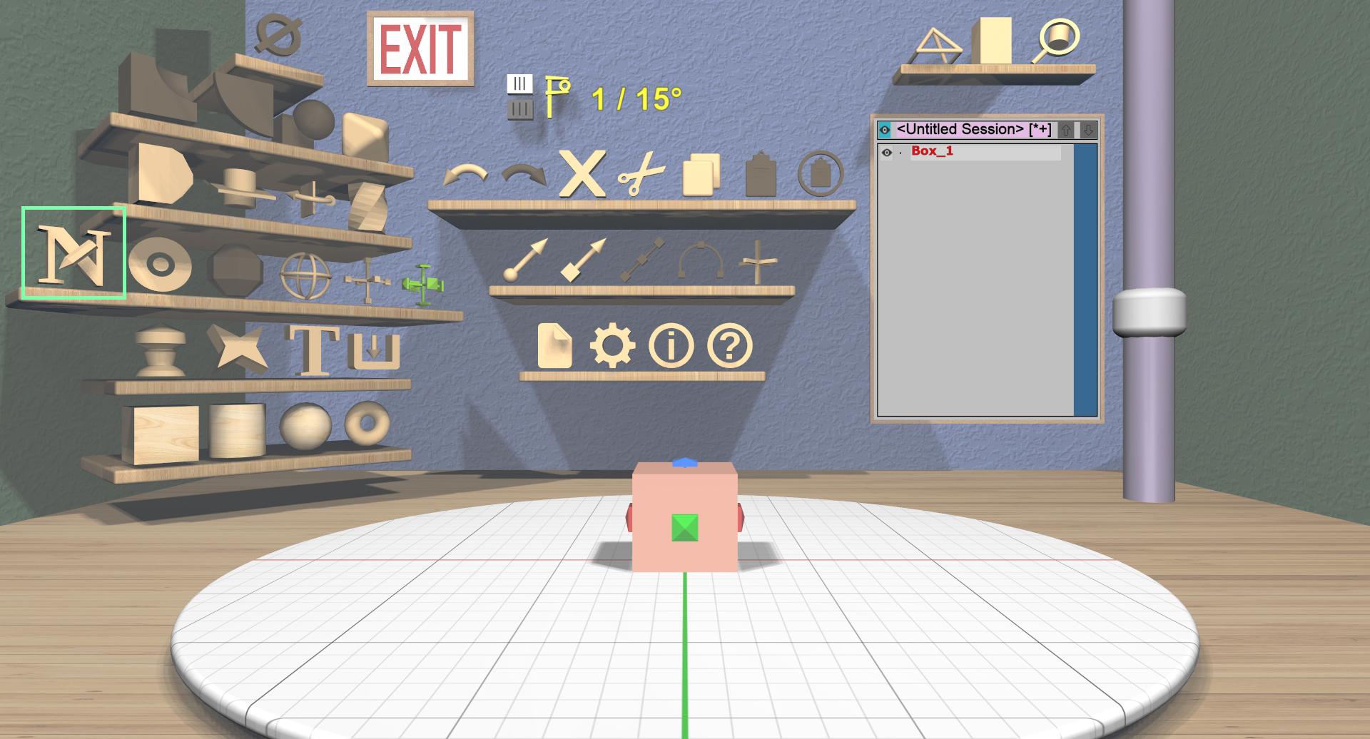
Click on the 3D cylinder icon on the bottom-left shelf to add a cylinder. Like the torus, the cylinder has specialized handles for changing the top and bottom diameters, but you won’t need them right now.

Next, select the Scale Tool from the General Tools shelf. This will attach a bunch of scaling widgets to the cylinder as shown here.
Drag the top (green) scaler down until the height of the cylinder is 3 units.
Combine the two Models to Create the Doorstop
The next step is to select both models. Since the cylinder is already selected, you just need to add the torus to the selection. You can do that in any of these ways:
Shift-click on the torus model.
Double-click on the torus model
Shift-click or double-click on the name of the torus (Torus_1) in the Tree Panel on the back wall.
Drag a rectangle in the Tree Panel that includes both model names.
Use the Ctrl-A select-all shortcut.
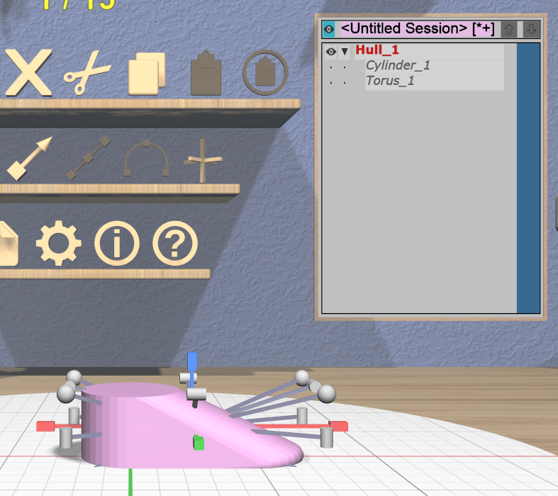
With both models selected, click on the Combine Hull icon on the Model Combining shelf. This creates a new model whose surface is a convex hull surrounding both selected models. You can see in the Tree Panel that the new model is named Hull_1 and that the two models it was created from appear as indented children.
Change the Model Name
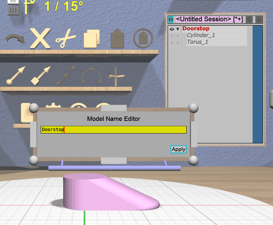
This is not a necessary step, but it will make the next step (exporting) easier. With the hull model selected, click on the Name Tool icon from the General Tools shelf. This will bring up a 2D panel for editing the model’s name.
Click in the text input area to activate it, and change the name of the model to Doorstop. Click the “Apply” button to change the model name; the new name should be shown in the Tree Panel.
Export the Model for 3D Printing


Exporting is done with the Session Panel that you saw when you started the application. Bring the panel up by clicking on the Session Panel icon on the Session shelf. Click on the “Export selection” button, which will open a File Panel that will let you select a file to export to, as shown here.
This panel is a fairly standard file browser. The default location for exported files is your home directory; this can be changed in the Settings Panel. The default name for the file will be the same as the name of the model, which is why renaming the model made sense.
A model can be exported as either text or binary STL using the dropdown at the top right of the panel.