Tools
Tools attach to selected models in the scene, adding interaction to perform a specific type of editing.
Tools are divided into two categories:
A general tool can be attached to any model, regardless of its type (except for the Complexity Tool).
A specialized tool can be applied only to a model of a specific type. It is used to modify unique editable features of that type of model.
Some tools add interactive 3D handles around or above the primary selection; others use 2D panels for editing.
Attaching and Switching Tools
EasyMaker3D maintains a current general tool, which is usually the last general tool that was used. The Translation Tool is the default current general tool when the application starts. You can switch to any other enabled general tool by applying the corresponding tool action. The Switch To Next Tool and Switch To Previous Tool actions also allow you to rotate through the available general tools.
If a specialized tool is available for the current selection, you can toggle between the current general tool and that specialized tool with the Toggle Specialized Tool action. Note that the Space shortcut is an easy way to apply this action.
As mentioned previously, creating a new model that has a corresponding specialized tool automatically attaches that tool so you can edit the model. If the new model has no specialized tool, the current general tool will be attached.
When changing the current selection, the following rules apply:
If the last attached tool was a specialized tool and all selected models support the same specialized tool (not necessarily the current one), that tool will be attached to the primary selection.
In all other cases, the current general tool will be attached to the primary selection.
General Tools
With the exception of the Complexity Tool, any of the following general tools can be attached to all selected models.
Color Tool
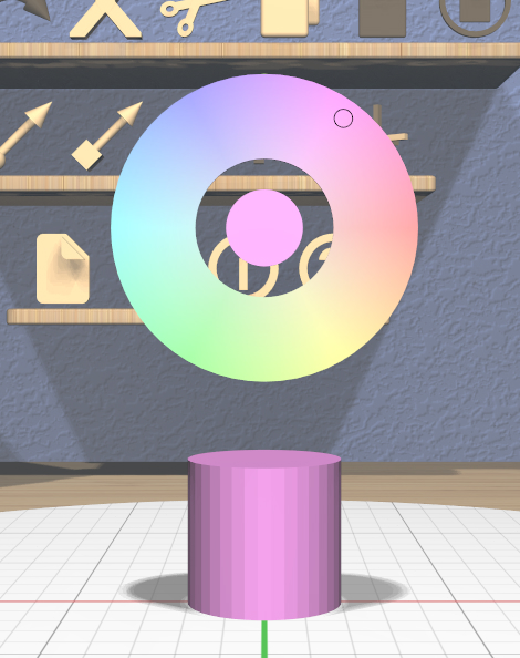
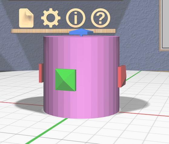
The Color Tool changes the color of all selected models. The interface for the tool is placed above the primary selection as shown in this image. The disc in the center of the tool shows the current color of the primary selection, as does the position of the small marker in the outer ring. Clicking or dragging anywhere in the ring moves the marker and changes the color of all selected models.
Colors have no real effect on the 3D-printed model, but they can be used to distinguish different parts while editing. Or just to make things look nicer.
VR Only
Grip dragging can also be used to change the color. The relative position of the controller is used to move the marker around the ring.
Complexity Tool
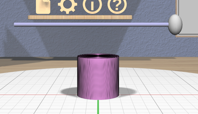
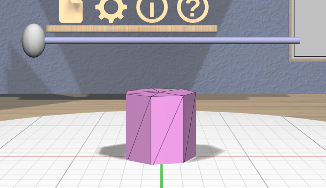
The Complexity Tool appears above the primary selection and can be used to change the number of triangles used in the meshes that represent all selected models. For models with curved surfaces, changing the complexity will obviously affect the smoothness of the model.
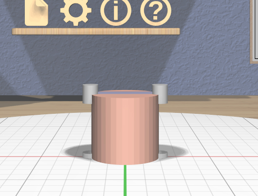
The tool consists of a single horizontal 3D slider. Dragging the slider handle changes the number of triangles used for all affected selected models. These images show two positions of the handle applied to a Cylinder model’s complexity.
Some notes about this tool:
The Complexity Tool has effect only on the following model types: Cylinder, Sphere, Torus, RevSurf (surface of revolution), Text, and Twisted model. The tool is disabled if the selection contains only models of other types.
If you want to change the complexity of a child model of a converted model or combined model of any type you can select the child or children and apply the complexity change. The parent model will update appropriately when its children are no longer selected.
Showing model edges can help you see the triangles more clearly as in these images.
You can use complexity to create models representing certain basic shapes. The lowest complexity Cylinder model is a triangular prism, and the lowest complexity Sphere model is an octohedron.
VR Only
Grip dragging also works; the relative position of the controller moves the handle.
Name Tool
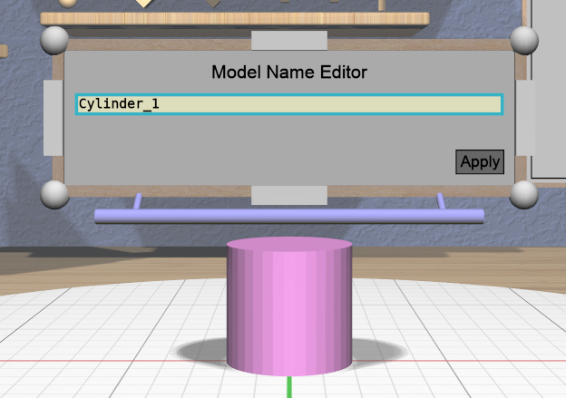
The Name Tool is a panel-based tool that lets you edit the name of the model that is the primary selection. A model’s name can help ypu distinguish its purpose or role, and is used as the default file name for STL export. Model names can be seen in the Tree Panel.
When attached to a model, the Name Tool displays a Name Tool Panel above the model. This panel has a text input field that responds to the mouse and keyboard to edit the name along with an “Apply” button that applies the changed name to the model. It will not let you apply an invalid name (empty or with leading or trailing whitespace) or a name that is already used by another model.
VR Only
If you are using the application in VR with the headset on, activating the text input field will bring up a panel with the virtual keyboard to allow text to be edited with the controllers.
Rotation Tool
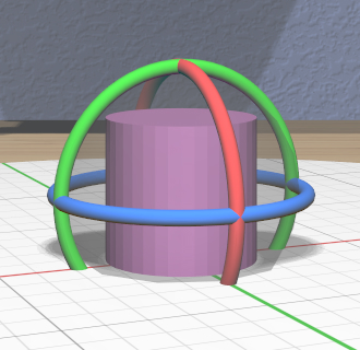
The Rotation Tool lets you rotate selected models. It has three color-coded rings for rotating about the principal axes and a translucent central sphere for applying free spherical rotation.
Color-coded angular feedback shows the current rotation angle or angles during an interactive drag with the tool. The rotation angle is snapped to the current precision level setting and snaps to the current Point Target direction if the target is visible.
The primary selection is always rotated about its center point. If multiple models are selected, secondary selections are also rotated around the the center of the primary selection. However, modified-dragging the Rotation Tool causes each model to be rotated in place about its own center.
The Axis-Aligned toggle affects how the Rotation Tool is attached to the primary selection. If the toggle is not active, the rings of the tool will align with the principal axes of the selected model. If the toggle is active, the rings will align instead with the principal axes of the stage.
VR Only

Grip dragging uses the orientation of the VR controller to define the rotation. A special rotation grip hover guide will be used for each controller to show which part of the Rotation Tool will be activated for a grip drag, as follows.
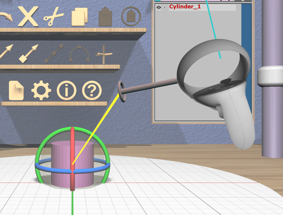
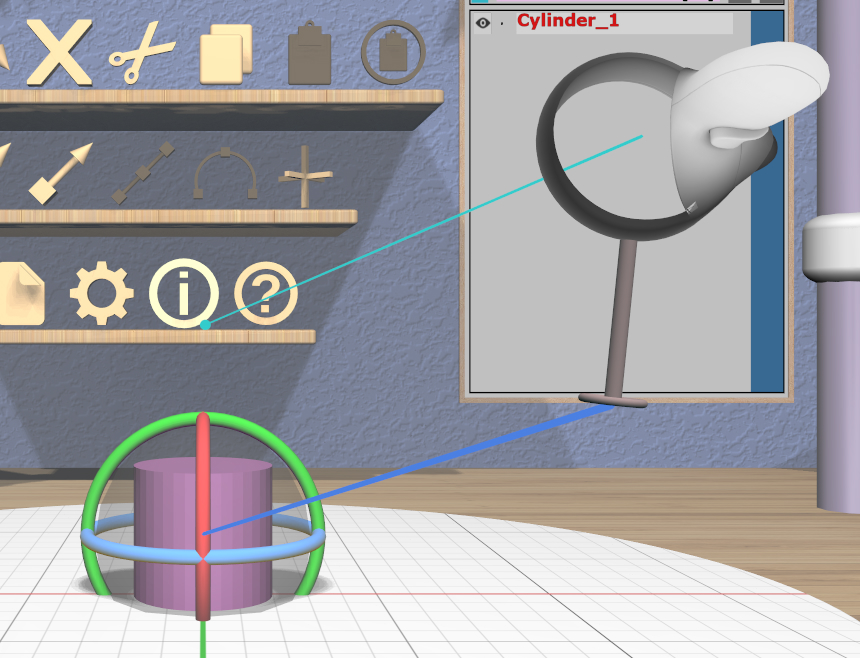
When the ring on the guide is close to aligning with any of the axis rings on the Rotation Tool, the guide will show a color-coded connection to that ring. In the left image here, the ring is close to aligning with the red X-axis rotation ring of the Rotation Tool, so a red connection appears. In the center image, it is close to aligning with the blue Z-axis ring. In any other orientation, the guide will show a yellow connection to the center sphere as in the right image.
If a ring is hovered, grip dragging by rotating the controller parallel to the ring rotates the model(s) in the same direction. When no ring is selected, grip dragging will rotate the model(s) by the free controller orientation.
Scale Tool
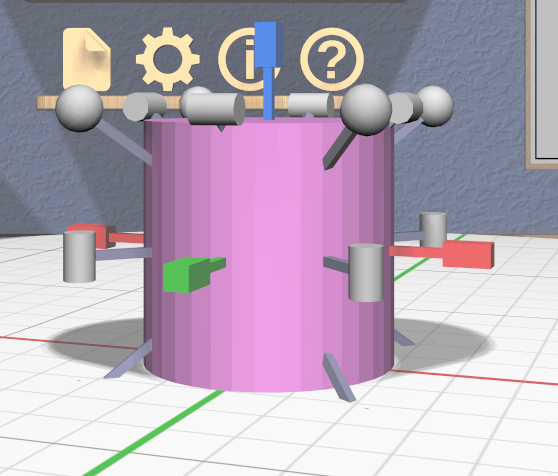
The Scale Tool lets you change the size of selected models. It has fifteen 3D scalers, each of which is a resizable stick with an interactive handle at each end. The handles are shaped to help indicate how they scale the model:
Three color-coded scalers are aligned with the coordinate axes of the model. These scale (nonuniformly) in a single dimension. Each handle of these scalers is a rectangular box that is longer in the dimension that will be scaled.
Eight scalers cross diagonally through the centers of edges. These scale nonuniformly in two dimensions. The handles of these scalers are cylinders that are aligned with the two scaled dimensions.
Four scalers pass diagonally through the corners of the model’s bounds. These scale uniformly in all three dimensions. The handles of these scalers are spheres to indicate the uniform scale.
Any dimension being scaled follows the current precision level and snaps to the current Edge Target length if the target is active. Color-coded linear feedback shows the current relevant dimension(s) of the primary selection during a drag.
There are two scaling modes:
Asymmetric scaling resizes the model about the opposite point. That is, when you drag a scaler handle, the handle on the other end stays fixed. This is the default scaling mode when dragging a handle.
Symmetric scaling resizes the model about its center. When dragging a scaler handle in this mode, the handle on the opposite side moves the same amount in the other direction. modified-dragging a scaler handle performs symmetric scaling.
Keep in mind that scaling a model’s height symmetrically can cause it to extend under the stage.
If multiple models are selected, all secondary selections are scaled in place in their local orientations by the same ratio applied to the primary selection. The Axis-Aligned toggle has no effect on the Scale Tool, since using different axes might cause confusing shearing to occur.
VR Only

Grip dragging uses the orientation of the VR controller to select a scaler handle to activate. The hover guide for each controller will show a color-coded connection to the handle closest to the guide’s orientation, if any.
In the left image, the hover guide is close to being aligned with the red X dimension scaler, so grip dragging will activate that scaler. In the right image, the guide is close to aligned with a diagonal uniform scaler, so it will be activated for grip dragging.
Translation Tool
The Translation Tool lets you change the position of selected models. It has three color-coded double-ended 3D sliders along each of the principal axes. Dragging the handle at either end translates all selected models along the corresponding axis.
Color-coded linear feedback shows the current translation distance during a drag. Translation distances follow the current precision level setting. Translation also snaps to the current Point Target position if the target is active. Snapping is done when the minimum, center, or maximum value of the primary model’s bounds in the translated dimension is aligned with the target’s position.
The Axis-Aligned toggle affects how the Translation Tool is attached to the primary selection. If the toggle is not active, then the sliders will always be aligned with the principal axes of the primary model. If the toggle is acive, the sliders will align instead with the principal axes of the stage.
VR Only
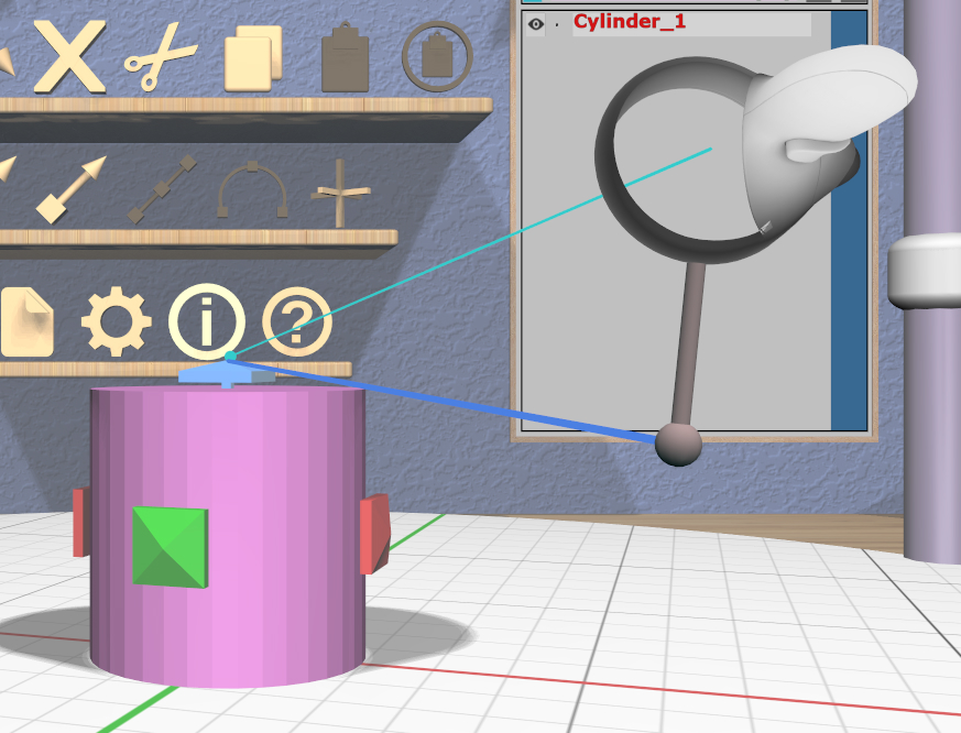
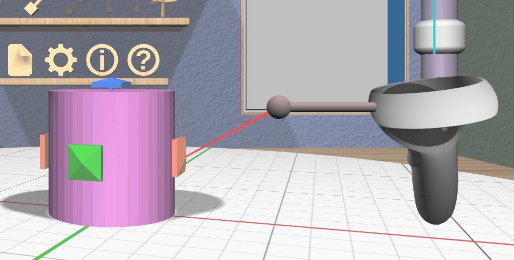
Grip dragging uses the orientation of the VR controller to choose a translation axis. The hover guide for each controller will show a color-coded connection to the handle closest to the guide’s orientation, if any, as shown in the images.
Specialized Tools
The following sections describe the various specialized tools that are used to edit specific types of models. Each specialized tool can be attached to the current selection only if all selected models are of the correct type for that tool.
For more information about each specialized tool that uses a panel for its interface, see the corresponding panel documentation.
Bevel Tool
The specialized Bevel Tool is a panel-based tool used to edit the bevel profile for one or more Beveled models. A Beveled model can be created from another model by applying the Convert Bevel action. Attaching the Bevel Tool displays a Bevel Tool Panel above the primary selection. Changes to the bevel profile in the panel are applied to all selected Beveled models.
Clip Tool
The specialized Clip Tool allows you to slice away parts of selected models by using a clipping plane. It is enabled when all of the selected models are Clipped models. You can convert any model to a Clipped model with the Convert Clip action.
The default clipping plane for a new Clipped model clips away the top half of the primary selection, however it is oriented. The Clip Tool is then attached to this plane to let you edit it. Whenever the Clip Tool is attached, it aligns itself with the clipping plane already applied to the primary model.
This tool has two interactive parts:
A translucent quadrilateral showing the position and orientation of the clipping plane relative to the primary selection. This plane can be rotated around its center to change the orientation of the clipping plane.
An arrow indicating the normal to the clipping plane. The part of the selected model(s) on the side of the plane with the normal is clipped away. Dragging the arrow lets you translate the plane along the normal.
All selected Clipped models are clipped in real time by the current plane while you rotate or translate the plane as shown here.
Translating the plane by dragging the arrow is limited by the extents of the primary model; it will not let you move the plane completely off this model, since that would leave either nothing or the entire model. While translating, the plane snaps to the Point Target position if the target is active and also to the center of the primary selection. The plane will change color to the active target color when it is snapped to either point. Modified-dragging the arrow deactivates any snapping.
When rotating the plane, the plane normal will snap to the Point Target direction if the target is active or to any of the principal axes. If the Axis-Aligned toggle is active, the principal axes of the stage are used; otherwise, the local axes of the primary model are used. The plane normal arrow changes color when snapped to either the target color or the color corresponding to a principal axis. Modified-dragging when rotating the plane deactivates any snapping.
VR Only
Grip-dragging works for both translation and rotation. If the controller is oriented so that the hover guide is nearly parallel to the plane normal arrow, grip dragging will translate the plane along the normal based on the controller position. Otherwise, grip dragging will rotate the plane based on the controller orientation. Snapping occurs as above unless modified-dragging.
CSG Tool
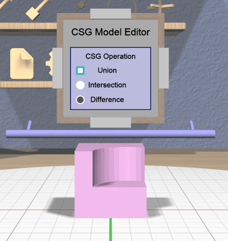
The specialized CSG Tool is a panel-based tool used to change the CSG operation applied to one or more CSG models. Attaching the CSG Tool displays a CSG Tool Panel above the primary selection. Changes to the CSG operation in the panel are applied to all selected CSG models.
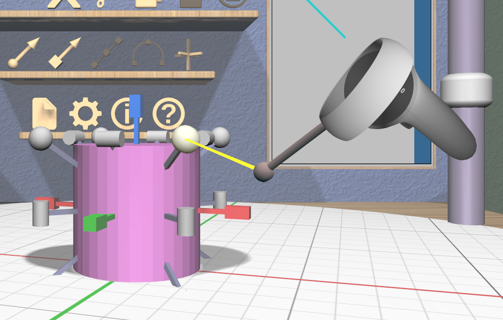
Cylinder Tool
The specialized Cylinder Tool is enabled when all of the selected models are Cylinder models. It allows you to change the top and bottom diameters of all selected Cylinder models to create cones or truncated cones.
The Cylinder Tool has two scalers, each of which is a resizable stick with an interactive handle at each end. The handles work symmetrically; dragging either handle changes the corresponding diameter of the selected Cylinder models.
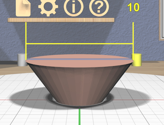
The diameter being modified follows the current precision level setting and also snaps to the current Edge Target length if the target is active. Linear feedback shows the current size of the diameter during a drag as shown here.
VR Only
Grip-dragging also works with the scalers. The relative vertical position of a controller chooses the top or bottom scaler.
Extruded Tool

The specialized Extruded Tool is a panel-based tool used to edit the profile used for one or more Extruded models. Attaching the Extruded Tool displays a Extruded Tool Panel above the primary selection. Changes to the extrusion profile in the panel are applied to all selected Extruded models.
Import Tool
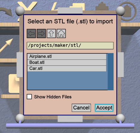
The specialized Import Tool is a panel-based tool that is enabled if there is exactly one Imported model selected. It has three basic uses:
Choosing the initial file to import the model data from, right after creating the Imported model with the Create Imported Model action.
Re-importing the model data from the same file after the file has changed.
Changing the file to import the model data from.
The Import Tool displays a Import Tool Panel above the selected model. Accepting the same file for an Imported model will re-import the data. Choosing a different file will load the data from that file. Any errors during data import will be displayed in a Dialog Panel.
Mirror Tool
The specialized Mirror Tool is enabled when all of the selected models are Mirrored models. You can convert any model to a Mirrored model with the Convert Mirror action. The default mirroring plane is oriented with the primary selection to mirror its local X (left-to-right) axis as shown here.
The Mirror Tool has the same interface as the Clip Tool for editing the mirroring plane (including in VR); refer to that tool for details. For example, you can rotate the plane to mirror vertically instead of horizontally as shown here.
Note that translating the mirroring plane results in the primary selection moving to compensate. Additionally, all secondary selections are mirrored across the same plane, so they will move to the other side of it.
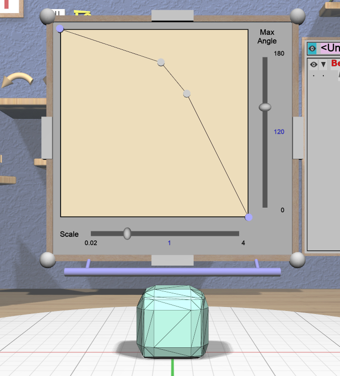
RevSurf Tool
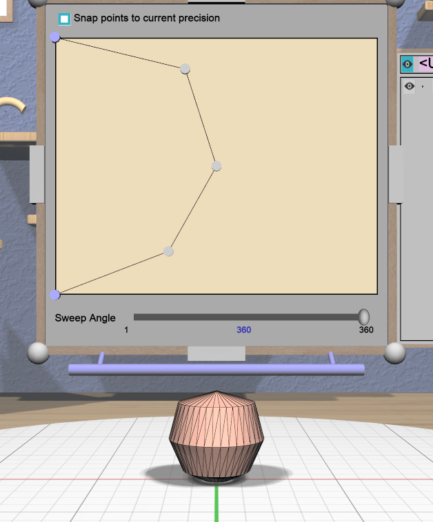
The specialized RevSurf Tool is a panel-based tool used to edit the revolved profile for one or more RevSurf models. Attaching the RevSurf Tool displays a RevSurf Tool Panel above the primary selection. Changes to the revolved profile in the panel are applied to all selected RevSurf models.
Torus Tool
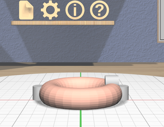
The specialized Torus Tool is enabled when all of the selected models are Torus models. It allows you to change the inner and outer diameters of all selected Torus models.
The Torus Tool has two scalers, each of which is a resizable stick with an interactive handle at each end. The handles work symmetrically; dragging either handle changes the corresponding diameter of the selected Torus models. The scaler for the outer diameter is aligned horizontally with the X axis, and the scaler for the inner diameter is aligned vertically with the Z axis.
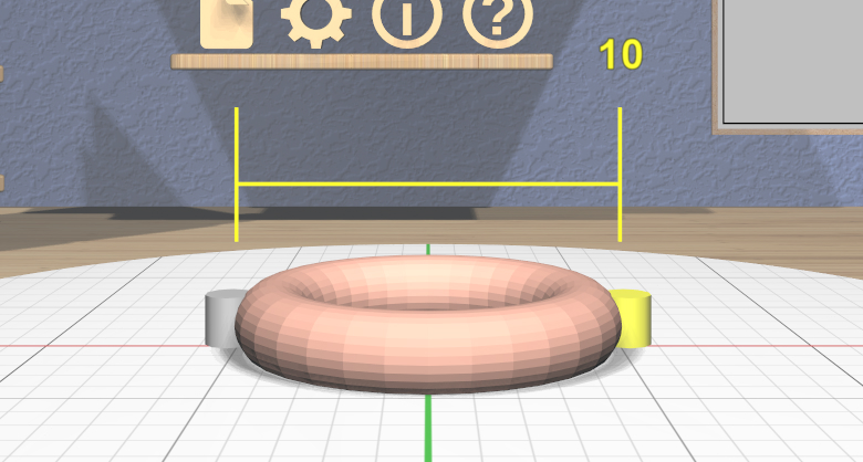
The diameter being modified follows the current precision level setting and also snaps to the current Edge Target length if the target is active. Linear feedback shows the current size of the diameter during a drag as shown here.
If the inner diameter is increased sufficiently, the outer diameter will be increased as well to keep the torus from intersecting itself. Reducing the inner diameter during the same drag operation will reduce the outer diameter as well up to its previous size.
VR Only
Grip-dragging also works with the scalers. The relative orientation of the grip hover guide on the controller (closer to horizontal or vertical) chooses the outer or inner diameter scaler.
Text Tool
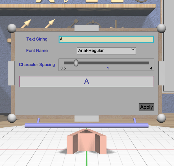
The specialized Text Tool is a panel-based tool used to edit one or more RevSurf models. Attaching the Text Tool displays a Text Tool Panel above the primary selection. The panel lets you change the text string, font, and character spacing. Clicking the “Apply” button in the panel applies all changes to all selected Text models.
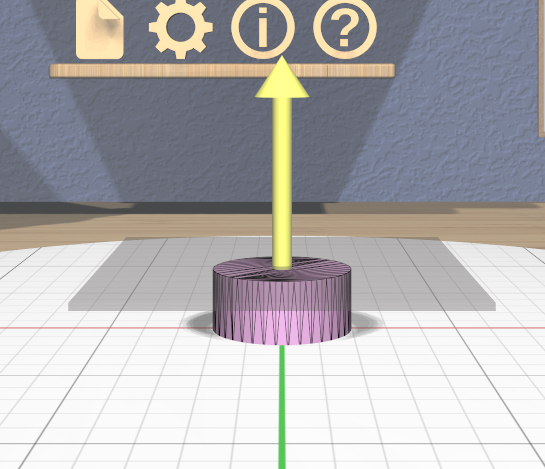
Twist Tool
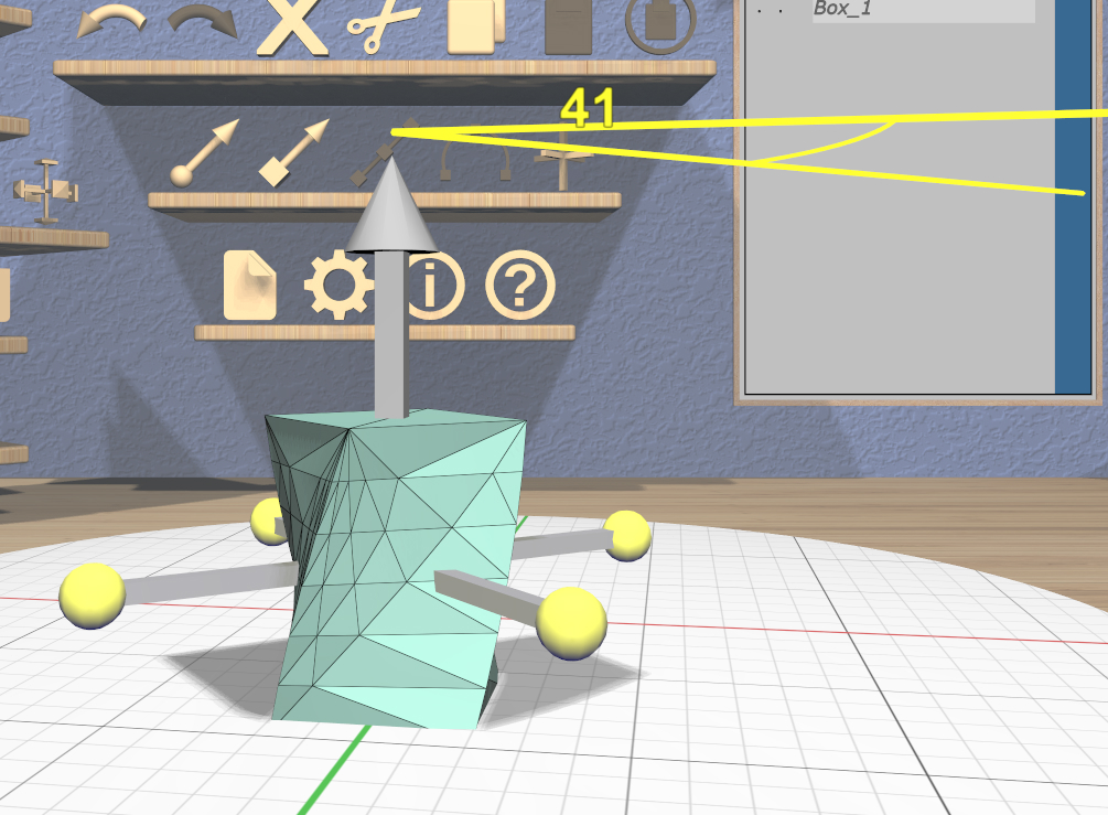
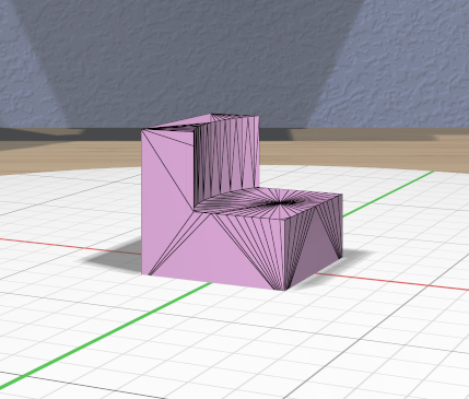
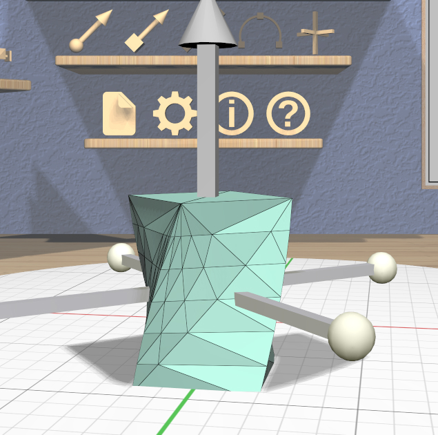
The specialized Twist Tool allows you to twist the vertices of a model around an axis. It is enabled when all of the selected models are Twisted models. You can convert any model to a Twisted model with the Convert Twist action.
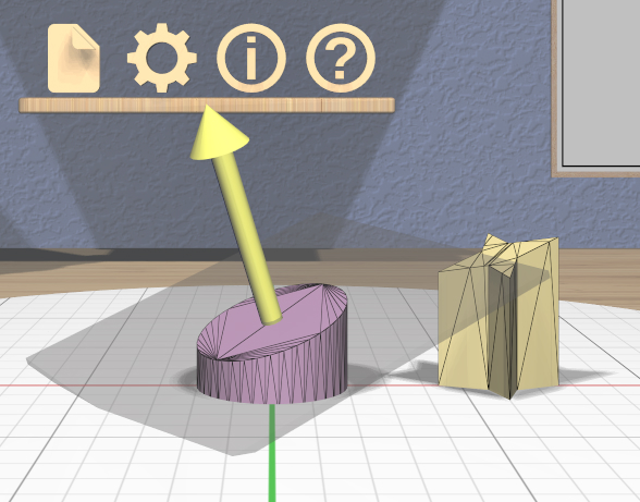
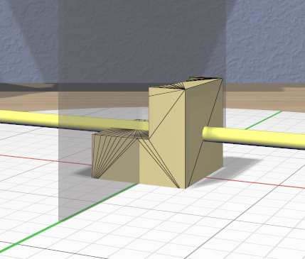
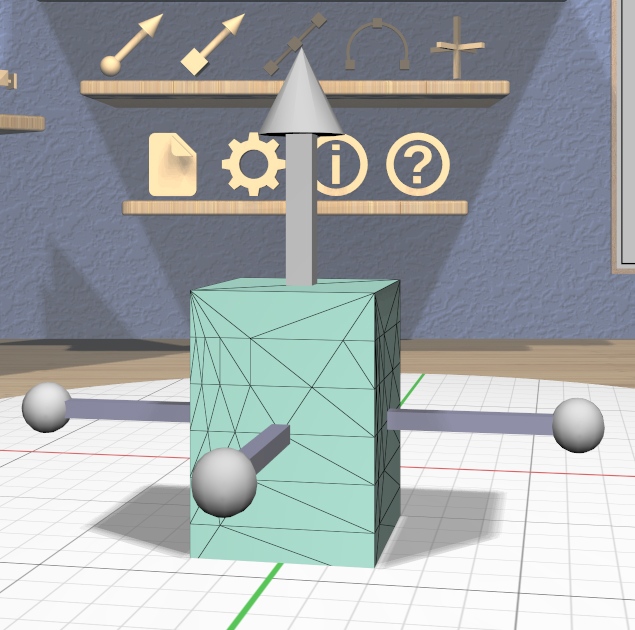
The Twist Tool displays an arrow showing the twist axis and a ring of four spherical handles that can be rotated around the axis to modify the twist angle. The arrow has a cone handle at one end and a box handle at the other. Twisting holds the mesh vertices at the base (box end) of the axis are held in place while the mesh vertices at the other end are twisted around the axis by the twist angle. All mesh vertices between those extremes are twisted proportionally. The right image here shows a Box model being twisted.
- The Twist Tool supports three types of interaction:
Dragging any of the spheres around the axis modifies the twist angle. Feedback shows the current angle, which is snapped to the current angle precision level setting as shown above.
Dragging either handle at the ends of the axis arrow rotates the twist axis.
Dragging any other part of the arrow translates the twist axis perpendicular to the axis direction.
All selected Twisted models are updated in real time when any of these occur.
When rotating the axis, the axis direction will snap to the Point Target direction if the target is active or to any of the principal axes. If the Axis-Aligned toggle is active, the principal axes of the stage are used; otherwise, the local axes of the primary model are used. The axis arrow changes color when snapped to either the target color or the color corresponding to a principal axis. Modified-dragging when rotating the axis deactivates any snapping.
While translating the axis, it snaps to the Point Target position if the target is active and also to the center of the primary selection. The axis will change color to the active target color when it is snapped to either point. Modified-dragging the axis deactivates any snapping.

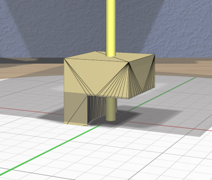
Note that a Twisted model is affected by the Complexity Tool. Increasing the complexity of a Twisted model increases the number of slices (and vertices) in the direction of the axis as shown here. Use caution, because the slicing operation and the resulting twist operations can get pretty slow for high complexity values. Also note that changing the complexity of the original model the twist is applied to may also affect the twist.
VR Only
Grip-dragging works for rotating the axis and twisting. If the controller is oriented so that the hover guide is nearly parallel to the axis direction (or its opposite), grip dragging will twist around the axis (by rotating the controller appropriately). Otherwise, grip dragging will rotate the axis direction based on the controller orientation. Snapping occurs as above unless modified-dragging.