Creating Models
EasyMaker3D supports a variety of model types. Most have a specialized tool designed specifically for editing them. Some (such as Sphere and Box models) have no specialized tools because there is nothing that cannot be modifed with a general tool].
Model Types
Models can be divided into three basic categories:
Primitive models are created from scratch or imported from STL files.
Combined models are created by combining other models in different ways. The resulting model may or may not have a specialized tool associated with it.
Converted models are created by converting other types of models in order to apply a particular specialized tool. For example, if you want to create beveled edges on a Box model, you first convert it to a Beveled model, then use the specialized Bevel Tool to modify the bevel.
These are all described in more detail in the following sections.
Primitive Models
First row:
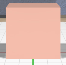
A Box model represents a 3D box with the length of all sides equal to 4 units by default. There is no specialized tool for a Box.
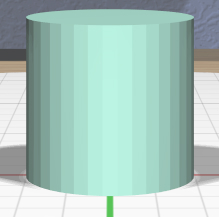
A Cylinder model represents a closed cylinder that by default has a diameter and height of 4 units. Its axis of symmetry is aligned with the +Z (“up”) axis. The specialized Cylinder Tool allows you to change the top and bottom diameters independently.
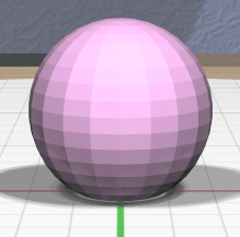
A Sphere model represents a sphere that has a diameter of 4 units by default. There is no specialized tool for a Sphere.
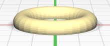
A Torus model represents a torus that by default has an outer diameter of 4 units and an inner diameter (height) of .8 units. Its axis of symmetry is aligned with the +Z (“up”) axis. The specialized Torus Tool allows you to change the outer and inner diameters independently.
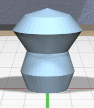
A RevSurf model represents a closed surface of revolution created by rotating a 2D profile about the Z (“up”) axis. The default profile consists of 3 points (the minimum allowed) that forms a surface with the widest diameter of 4 units and a height of 4 units. The specialized Surface of Revolution Tool lets you edit the profile and also the sweep angle of the surface.
Second row:
An Extruded model represents a closed profile extruded along the +Z (up) direction. Its default height is 4 units. The specialized Extruded Tool allows you to edit the extruded profile.
A Text model represents extruded 3D text, which is laid out by default at the origin along the +X axis, extruded 4 units along the +Z (up) direction. It is sized by default so that the characters are approximately 4 units in the Y dimension. The specialized Text Tool allows you to change the text string, font, and character spacing.
An Imported model is read from an STL file. The specialized Import Tool is used to select or change the file to import from. Note that a newly-created Imported model will be displayed as a dummy tetrahedron with an invalid color until a valid STL file has been selected with the Import Tool. Also note that many, many publicly-available STL models are not valid meshes (watertight, not self-intersecting) and will also appear with the invalid color. The Info Panel can tell you why the mesh is invalid.
New primitive models are placed at the center of the stage unless the Point Target is active, in which case the new model is placed to align with it.
Combined Models
One of the main features of EasyMaker3D is the ability to create new models by combining other models. When models are combined, the original models become children of the combined model in the model hierarchy (as shown in the Tree Panel). The original models can be modified later, and the changes will be reflected in the combined model.
A combined model is defined in its own coordinate system, originally aligned with the stage. That is, if you take two rotated models and create a combined model from them, the combined model’s axes will not be rotated like either of the parts; they will align with the stage.
Constructive Solid Geometry (CSG)
A useful way to create a new model is to apply any of the three constructive solid geometry (CSG) operations to two or more models:
A CSG Union is formed by adding all selected models together.
CSG Intersection uses the intersection of all selected models.
CSG Difference subtracts all secondary selections from the primary selection. Unlike union and intersection, CSG difference is asymmetric, so the selection order really matters.
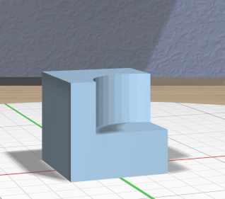
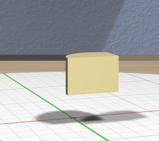
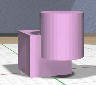
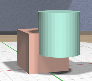
These images show the original operand models, a box and a cylinder, and the resulting CSG union, intersection, and difference (cylinder subtracted from the box).
Note that in some cases using the Clip Tool may be a sufficient and simpler method of geometric editing.
Convex Hull
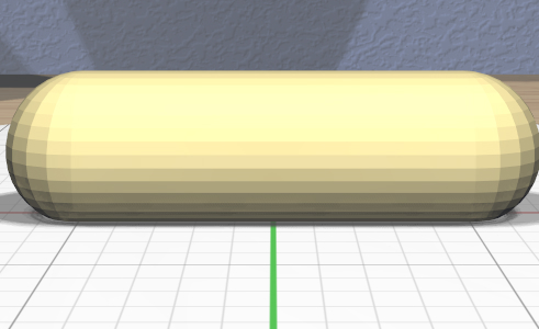
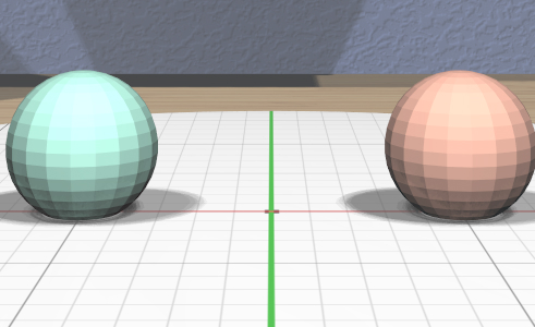
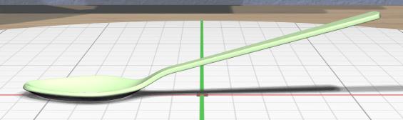
Another way to combine models is with the convex hull operation, which creates a new model from the 3D convex hull of the selected models. This can be used to easily create different shapes. For example, here is an easy way to create a capsule by applying the convex hull operation to two spheres.
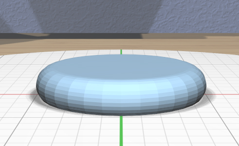
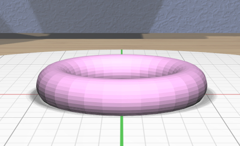
The convex hull operation can sometimes be useful to apply to a single model, if the model is not already convex. Here’s an example of creating a rounded disk as the convex hull of a torus.
Note that there is no specialized tool for a Hull model.
Converted Models
Certain operations require models to first be converted to a different type.
Each of these model types is created by selecting one or more models and clicking on the appropriate conversion tool icon. Once the conversion is done, you can use the corresponding specialized tool to edit the resulting models, as listed below.
Note that this two-step process (converting, then editing) makes it clear that a new type of model must be created in order to apply the editing operation. The converted model becomes a parent of the original model in the hierarchy (as shown in the Tree Panel). This scheme also simplifies the interface and also allows the original objects to be modified even after the conversion operation has been applied.
A Beveled model applies a bevel or other profile to edges of a model. The Convert to Bevel action is used to convert the models and apply a default bevel. The specialized Bevel Tool is attached to the selection to allow you to modify the bevel profile.
A Clipped model applies a clipping plane to a model. The Convert to Clipped action is used to convert the models and apply the default clipping plane that removes the top half of the primary model. The specialized Clip Tool is attached to let you modify the clipping plane.
A Mirrored model mirrors a model about a plane. The Convert to Mirrored action is used to convert the models and mirror them about the default mirroring plane (which mirrors left/right through the center of the primary model) and the specialized Mirror Tool is attached to let you change the plane.
A Twisted model twists the vertices of a model about an arbitrary axis. The Convert to Twisted action is used to convert the models and attach the specialized Twist Tool to let you change the axis and twist angle.
Note that a converted model synchronizes its transformations (scale, rotation, and translation) with the original model. Any changes made to the transformations for either the original or converted model are also applied to the other. One slight exception to this is the Beveled model, since the scale of the original model has to be applied before the bevel profile is applied. The scales in this case are kept in sync, but a scale applied to the Beveled model is applied after the beveling operation is applied.
Model Names
When EasyMaker3D creates a model of any type, a unique name is assigned to it automatically by affixing an underscore and a number to its base model type, such as Sphere_1 or Imported_13. Model names can be seen in the Tree Panel and edited with the Name Tool.
Model Colors
Reasonable colors are chosen automatically for new models created in the scene. The Color Tool allows you to change the color of any model for aesthetic reasons. (The colors have no effect on the 3D-printed model.)
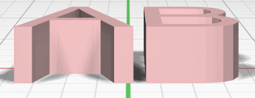
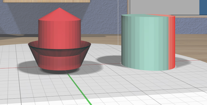
Two special model colors are outside the normal range as shown here:
Any model with an invalid mesh is colored like the model on the left to indicate that it will probably not print successfully. A mesh is invalid if it is not closed, has weird connectivity, or self-intersects.
If the build volume is visible, any part of any model that lies outside of it will be colored as shown on the right in the image. This indicates that the model will likely not be printed successfully.
When an invalid mesh is detected, it will retain the invalid mesh color until the problem is fixed. Changes made to such a model with the Color Tool will still take effect, but you will not be able to see them while the model is invalid. Also, some tools will be disabled when an invalid model is selected to avoid compounding the problem.
One exception is the convex hull operation, which is enabled even for invalid meshes. This can be used as a quick way to “fix” an invalid mesh if the hull is close to what you want.
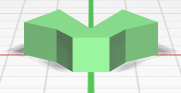
Model Edge Display
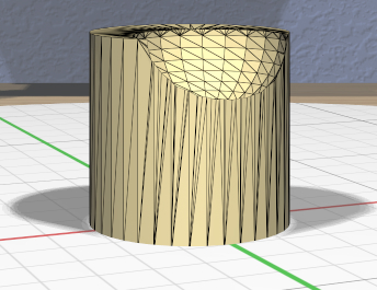
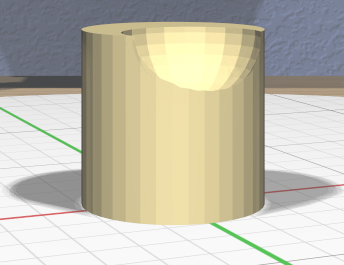
Clicking The Show Edges Toggle icon lets you display edges of your models as visible lines or hide them. Showing them can help you see how your models are tessellated into triangles for 3D printing or to help place the Edge Target.