Precision
EasyMaker3D offers several features to help you create 3D models with precise dimensions and placement.
Precision Level
EasyMaker3D provides a variable precision level to help you use exact values during drag operations. There are three precision levels, each affecting both linear operations (such as scaling and translation) and angular operations (such as rotation).
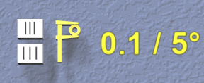
1 unit / 15°
.1 unit / 5°
.01 unit / 1°
Assuming centimeter units, the linear precision levels are then 1cm, 1mm, and .1mm, respectively.
Here is how to change the current precision level:
Click on one of the the two buttons on the Precision Control on the back wall of the work area. The top button increases to finer precision, and the bottom button decreases to coarser precision.
Use x and z keyboard shortcuts to increase and decrease levels, respectively.
VR Only
You can also click the Up or Down buttons on either VR controller trackpad or joystick to increase or decrease the current precision.
Note that the keyboard and controller shortcuts work even during drag and VR grip drag operations. Modifying the precision setting during a drag has the following effects:
Updates the text and buttons on the Precision Control.
Changes the precision of the current operation (position, size, etc.).
Changes the precision of the visual feedback for the current operation.
Changes the relative amount of drag motion. This may be startling at first, but makes sense when you try it out. For example, if you want to move an object exactly 5.45 units to the right, you start out with 1 unit precision and drag it 5 units. While still dragging, increase precision to .1 unit and drag it .4 units more. This uses the same amount of drag motion that 4 units would at 1 unit precision, so it’s much easier. Finally, increase precision again to .01 unit and drag another .05 units to the right, again with the corresponding amount of drag motion.
Once you get used to this, it becomes relatively easy to achieve precise dimensions and distances interactively.
Visual Feedback
Most interactive drag operations display some sort of visual feedback. Operations that are essentially linear show the current dimension of that change along a line, while rotations show the current angle. Multi-dimensional changes such as uniform scaling and spherical rotation show feedback in all affected dimensions. The precision of the feedback matches the current precision level.
Feedback is colored according to the coordinate system convention for the appropriate dimension(s). When a drag operation is snapped to a target, feedback is displayed in the active target color.
Targets
Precise interactive placement can be tedious, so EasyMaker3D offers extra help for some operations using targets. A target is a 3D object that you can place in the scene to affect future operations. Targets can be used to transfer information from one object to another, such as position, orientation, or size. This can be very useful, for example, to align objects precisely.
There are two targets available in the application:
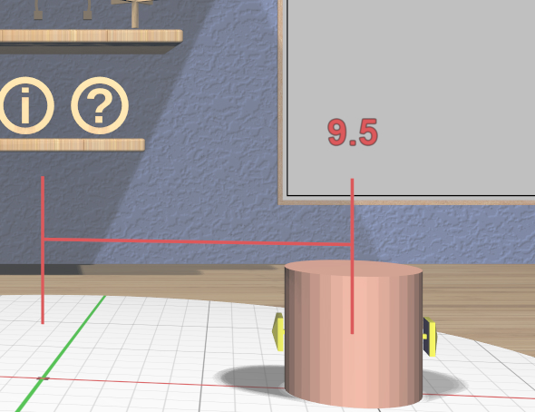
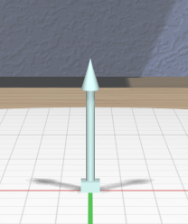
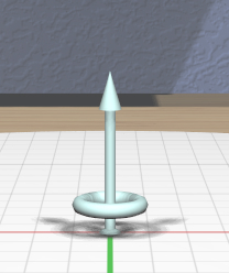
The Point Target represents a position (the base sphere) and a direction (the arrow). It also has a ring used for radial layout.
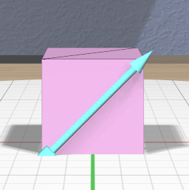
The Edge Target represents a length and a direction.
The ring on the Point Target is used for radial layout.
Targets must be active (visible) to have any effect. To activate or deactivate the Point Target, click on the Toggle Point Target icon. To activate or deactivate the Edge Target, click on the Toggle Edge Target icon.
Each target appears initially in the center of the stage. If a target is obscured by models, you can use the Tree Panel to hide those models temporarily.
Positioning Targets
Targets are positioned by dragging or modified-dragging them; they change to the active target color while the drag is in process. Targets can be placed either on the stage or any model in the scene. When dragging a target on the stage, the target will snap to grid locations based on the current precision level.
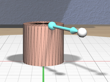
The Point Target can be dragged by any part (except the ring). When dragging over a model’s surface, the target location will snap to vertices of the model’s triangular mesh when close enough, based on the current precision level. When this occurs, a snap indicator (sphere at the tip of the target’s arrow) will appear.
Similarly, the Edge Target snaps to the closest edge of the model’s mesh, matching the length of that edge. (You may find it helpful to show model edges.) If the Edge Target is dragged from a model to the stage, it retains the length of the last edge it snapped to.
Clicking on the Edge Target reverses its direction, which can be useful when performing linear layout.
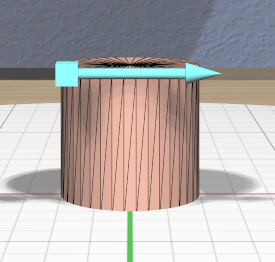
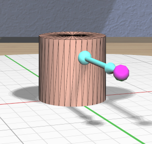
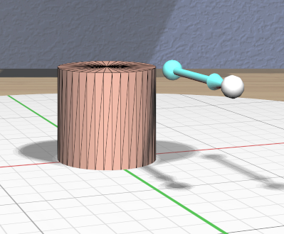
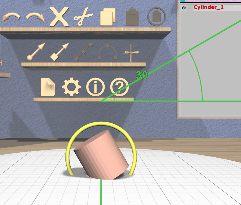
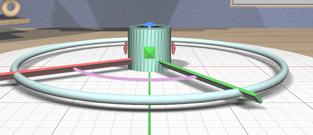
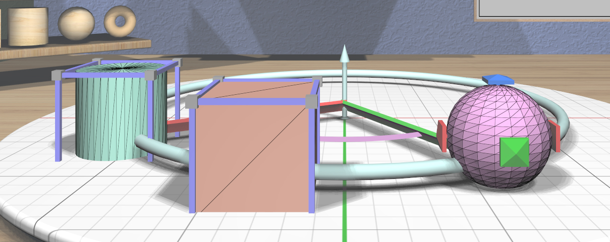
Modified-dragging either target over a model uses the rectangular bounds of the model instead of its mesh. The Point Target will snap to the minimum, maximum, and center values of the bounds in each dimension. You can use this feature to more easily attach the point target to important points on objects with asymmetric meshes. Similarly, the Edge Target snaps to edges of the of the model instead of its mesh; the target will snap to the nearest edge of the bounds. You can use this feature to easily set the edge target length to any dimension of a model’s bounds, such as the width of the cylinder shown here.
When modified-dragging the Point Target, the snap indicator sphere will appear when any snapping occurs, and is color-coded by dimension. If snapping occurs in two or three dimensions, the color will be the sum of the respective dimensions’ colors. In the above left image, the Point Target is snapped to the center of the front-right edge of the cylinder’s bounds. In the center image, the precision level has been increased to keep the target from always snapping to a bounds edge, and the target is on the center line of the front face of the bounds, but is not snapped in the Z (up) dimension.
Effects
When active, the Point Target and Edge Target affect certain drag operations, causing them to snap to the target values when specific conditions are met. When snapping occurs, both the target and the visual feedback change to the active target color. See the documentation for the individual tools for specific details of how they handle snapping.
When the Point Target is active, interactions that involve position (such as the Translation Tool) or orientation (such as the Rotation Tool) snap to the target’s position and direction as shown here.
Similarly, when the Edge Target is active, interactions that involve size (such as the Scale Tool) snap to the target’s length.
The Point Target can also be used for instantly positioning a model and has other features that let it be used be used for radial layout, described below. The Edge Target can be used for linear layout, also described below.
Layout
The Point Target can be used to lay out objects along a circular arc (radial layout), and the Edge Target can be used to lay out objects along a line (linear layout).
Radial Layout
The Point Target can also be used to lay out selected models in a circle or along a circular arc. All of the parameters of the layout are specified using the features of the target.
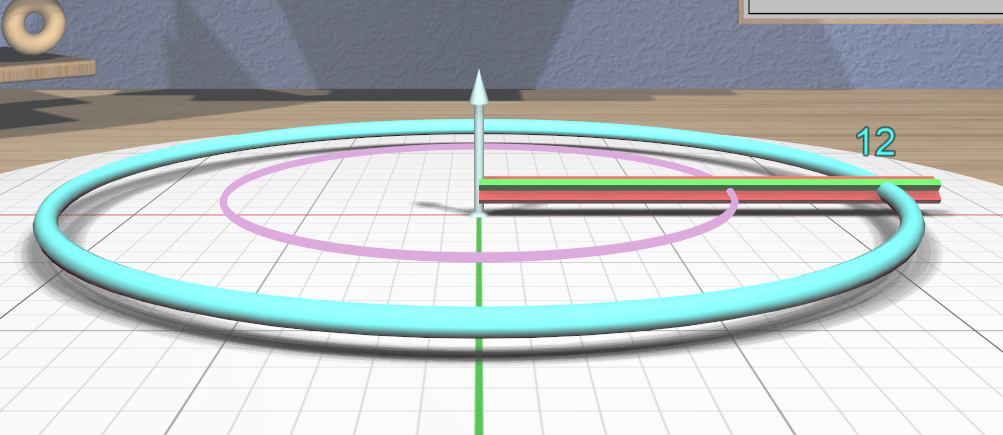
The radius of the circle or arc is specified by dragging the ring around the Point Target to the desired size. The radius adheres to the current precision level. You can drag the ring close to the target again to disable the radial layout features.
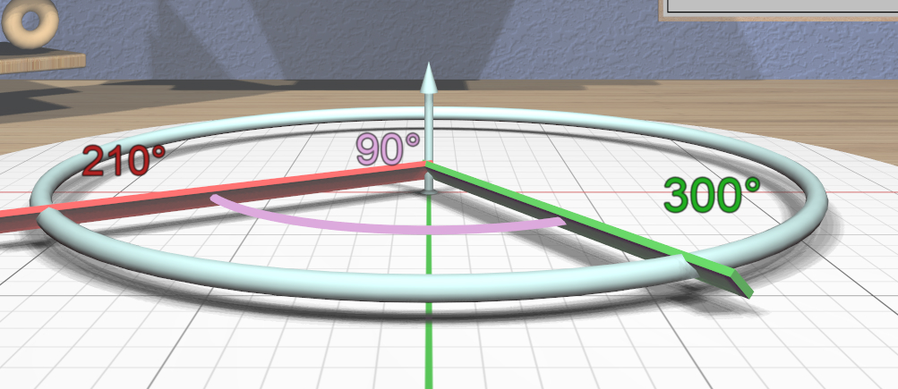
When the ring radius is large enough, two spokes appear to let you specify the starting and ending points on the circle. The green spoke defines the starting point of the circle or arc, and the red spoke defines the end. If you drag the green spoke, both spokes rotate around the circle. If you drag the red spoke, only it moves, allowing you to change the arc used for the layout. If you want to reverse the layout direction, drag the red spoke past the green one in the desired direction. As you drag either spoke, color-coded feedback shows the spoke angles and the subtended arc angle. The spoke angles also adhere to the current precision level
When the radius and spokes are correct, click on the Radial Layout icon to lay out the selected models. The primary selection will be moved to the point where the green starting spoke intersects the ring, and the secondary selections will be evenly spaced along the ring up to the red ending spoke, as shown here on the left. All selected models will have their “up” directions aligned with the Point Target direction.
As a special case, if exactly one model is selected, clicking on the Radial Layout icon will move the model to the Point Target location and align it with the arrow, as shown in the right image. This is true even if the radial layout features of the Point Target are not visible; this is an easy way to align objects.
Linear Layout
The Edge Target can be used to lay out two or more models along a line. The length and direction of the Edge Target determine the offset between models.
When two or more models are selected, clicking the Linear Layout icon lays out all of the models along a line. The primary selection is left in its original position. The center of the first secondary selection will be placed at the offset from the primary model’s center, and so on for subsequent selected models, in selection order.
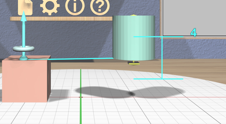
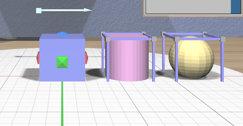
It may sometimes be useful to create a temporary model with the correct size as a layout aid. For example, suppose you want to lay out 3 models along the X direction with 6 units between their centers as in this image:
Create a box and scale it so that it is 6 units in size in X (using 1 unit precision level).
Activate the Edge Target and drag it onto one of the box edges in the X direction. Click on the Edge Target to reverse it if it is pointing in the opposite direction. The target should then be exactly 6 units in length and pointing in the correct direction.
Delete the box if you no longer need it.
Select the models you want to lay out in the correct order.
Click on the Linear Layout icon to lay them out.