Overview
EasyMaker3D helps you create models that you can then send to a 3D printer. It is designed to be relatively simple to use, even for someone with little to no 3D modeling experience. If you don’t want to deal with the steep learning curve of 3D modelers like Blender, you might find EasyMaker3D useful.
EasyMaker3D is inspired somewhat by OpenSCAD (my favorite program for creating 3D models). OpenSCAD is great if you don’t mind typing in numbers for everything and have a reasonable amount of 3D graphics experience. EasyMaker3D is designed to have a similar amount of power while still being useful to beginners.
Typical Workflow
Typical use of EasyMaker3D to create models for 3D printing involves the following steps:
Create one or more basic models of different types or import existing models in STL format.
Edit the models and/or combine them in different ways to create new models.
Export any of the resulting models to STL files to send to a 3D printer.
Because precision is extremely important when 3D printing, EasyMaker3D has several features that allow you to create models with exact dimensions, orientations, and positions. See the section on precision for details.
The Work Area
Because EasyMaker3D is designed to be used in VR as well as in a conventional mouse+keyboard environment, it cannot rely on typical menu-based interaction. Instead, it uses a fully 3D interface (with some 2D panels embedded in it).
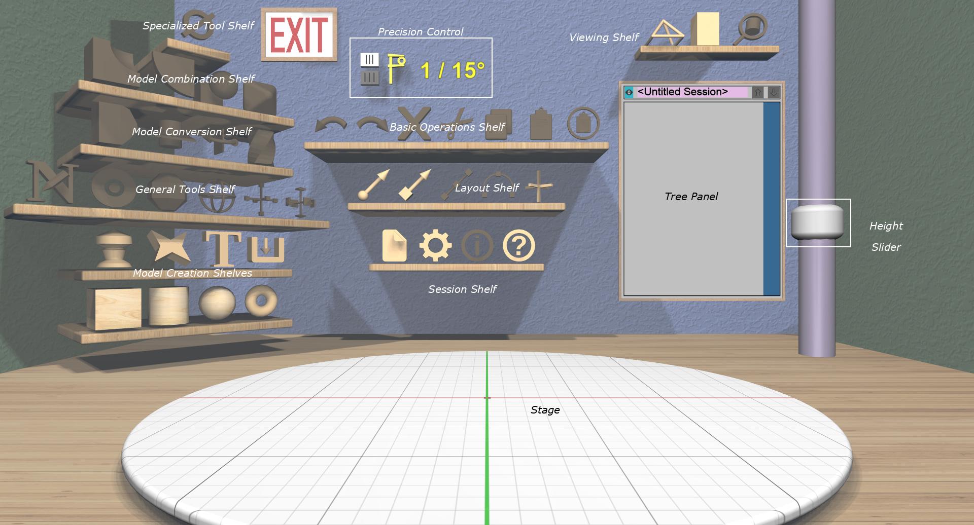
Elements of the EasyMaker3D work area.
The work area in EasyMaker3D is based conceptually on a virtual workshop containing these elements:
Four walls, a floor, and a ceiling, just to provide context for the room.
An exit sign. Clicking on this exits the application. If you have made any changes, you will be asked if you want to save your session first.
A large disc in the middle of the floor with a grid on it. This is the Stage on which models are built. It provides interaction for viewing the models.
A pole on the right with a Height Slider that can be used to change or reset the view height.
Several 3D icons organized into shelves. Each icon represents an action that makes some change to models or to the session state.
A Precision Control that shows the current interactive precision level with buttons to increase or decrease it.
The Tree Panel on the back wall that displays all models in tree form and allows you to interact with them.
Panels
Some interaction requires a more conventional interface; panels are used in these circumstances. A panel is a 2D rectangle that appears in the scene with various text inputs, sliders, and so forth. For example, when the application starts, the Session Panel appears to let you choose a session to start or continue. You can interact with panels with the mouse, keyboard, or VR controllers, just like the rest of the work area.
See the section on panels for specifics on interacting with panels.
Sessions
Most applications let you save your work as a data file and restore just the data when you restart, losing all context of how it was created and edited. EasyMaker3D, on the other hand, stores your session as a series of commands that have been executed along with some other program state. This means that you can save your session, quit, restart your session, and be back pretty much where you were. You can undo all of your work back to the beginning if you want to.
When you start the application, the Session Panel appears, which offers you the chance to continue the current session (if there is one), load a different session from a file, or start a brand new session. The default location of saved sessions is your home directory; this can be customized in the Settings Panel.
Certain other program state (such as whether targets and model edges are visible) is saved along with the session and will be restored when a session is loaded.
The name of the current session file, if any, is displayed at the top of the Tree Panel (without the “.ems” suffix). The name is followed by a string indicating whether the scene or settings have been modified.
Coordinate System, Units, and Dimension Colors
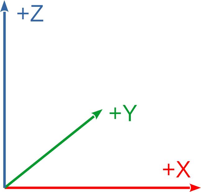
EasyMaker3D uses the same coordinate system that most 3D printing software uses: right-handed, with +X to the right, +Y away from the viewer, and +Z up. The top surface of the stage is at Z=0.
All dimensions in EasyMaker3D are essentially unitless, so you can consider them to be whatever is most convenient. The only times actual units are considered are:
When models are imported or exported from or to STL files.
When the 3D printer build volume is defined to show the extents of your 3D printer.
The Settings Panel allows you to specify how to convert units when importing and exporting, and also how large the build volume is in whatever units you would like to work in. For example, if you consider EasyMaker3D units to be inches and need to convert to millimeters for export (which is the standard for STL files), you can set that.
The default settings assume that EasyMaker3D units are centimeters and convert to and from millimeters (STL standard) on export and import.
Note that the grid on the stage has thin lines every 1 unit, with thicker lines every 5 units. The grid grows or shrinks when the stage is scaled so that you can always discern the absolute sizes of models on it. Also, the X and Y axes are colored red and green on the grid for reference.
Most everything in the application that aligns with the coordinate axes uses a standard RGB color scheme: X is red, Y is green, and Z is blue as in the diagram. This is true for axis-aligned parts of Tools and interactive visual feedback.
The Build Volume
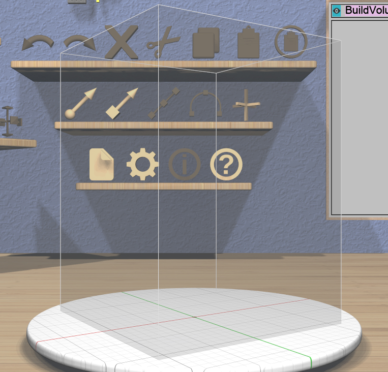
If you want to make sure that your models will fit within your 3D printer’s build volume, you can choose to display the build volume on the stage by clicking on the Build Volume Toggle icon on the Viewing Shelf. The build volume is rendered as a translucent box. You can specify the size of the build volume for your specific printer in the ref:Settings Panel <ug-settings-panel>.
When the build volume is visible, parts of models that lie outside it are rendered in a special color to warn you of potential printing problems.
VR and Non-VR Modes
Since most people do not have a VR setup, EasyMaker3D can operate without one, using the mouse and keyboard exclusively. This is referred to below as conventional mode.
If you do happen to have a VR headset, you can set it up as explained in the Quickstart. There are two ways to use it with the application:
VR mode refers to using the VR system with the headset on and controllers in your hand.
Hybrid mode is halfway between the other two: you have the VR system connected, but you are not wearing the headset. In this mode you can still use one or both controllers for interaction in the conventional window view.
Some VR experiences allow you or force you to walk around while using them. That wouldn’t make sense for this application, so it is designed to make everything useful from one spot. If you’re planning to use the VR mode, set it up for a comfortable, fixed standing or seated position. Note that the scene view is set up for sitting, so you may need to adjust your VR positioning for a different height if you prefer to stand.
VR Only
Note: any information in the rest of this guide that applies only to either of the two VR modes will be formatted like this paragraph. If you are not using a VR system, feel free to skip over these.